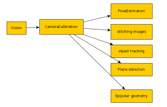
Calibrating is the process that we must to with every camera we have before using it for vision projects. Other articles describe this better than I can, but the idea is that every lens causes some distortion. We want to undo those imperfections, so we can more accurately handle the objects in the image. This is helpful for every vision task including OCR, pose estimation, object tracking...etc. If you want more information look for “homography” and “epipolar geometry” These require two matrices one called Camera Matrix and the other is the Distortion Coefficients.
Originally, I was following tutorials online for “calibrate camera with churaco board” the problem I ran into was that the openCV they used was OpenCV4.5 or OpenCV4.7 and the latest is OpenCV4.8.1, and in this latest version they made lots of changes to the Aruco object. This rendered all of the tutorials online outdated, so their code would not compile. I managed to get around this by using the C++ examples in the latest openCV repository. This meant I needed to compile from source.
Get Ubuntu Prerequisites
The first step is to make sure we have the prerequisites to build openCV from source. In a terminal paste the following block of text to fetch the needed files
sudo apt install -y python3-dev python3-pip python3-numpy build-essential libgtk-3-dev libavcodec-dev libavformat-dev libswscale-dev libv4l-dev libxvidcore-dev libx264-dev libjpeg-dev libpng-dev libtiff-dev gfortran openexr libatlas-base-dev libavcodec-dev libavformat-dev libswscale-dev libv4l-dev libdc1394-22-dev libgstreamer1.0-dev libgstreamer-plugins-base1.0-dev libatlas-base-dev libfaac-dev libmp3lame-dev libtheora-dev libxvidcore-dev libx264-dev libopencore-amrnb-dev libopencore-amrwb-dev libgphoto2-dev libeigen3-dev libhdf5-dev doxygen x264 v4l-utils # https://gist.github.com/Mahedi-61/804a663b449e4cdb31b5fea96bb9d561 |
Compiling OpenCV from source
To compile the code we’ll need to set up the folder structure:
opencv_build
opencv_build\opencv
opencv_build\opencv-contrib
to do this we run the following:
mkdir ~/opencv_build && cd ~/opencv_build git clone https://github.com/opencv/opencv.git git clone https://github.com/opencv/opencv_contrib.git
mkdir -p build && cd build
|
Before we actually tell the system to build the code, it is possible to enable CUDA, but I am using CPU only, so I don’t configure the CUDA feature. I also wanted to enable “PKGCONFIG” instead of using CMAKE files, which is the recommended way, I used pkgconfig to link the openCV libraries when I built the examples. So my make command, which you can paste into a terminal looks like:
sudo cmake -D CMAKE_BUILD_TYPE=RELEASE \ -D CMAKE_INSTALL_PREFIX=/usr/local \ -D OPENCV_ENABLE_NONFREE=ON \ -D INSTALL_C_EXAMPLES=ON \ -D INSTALL_PYTHON_EXAMPLES=ON \ -D OPENCV_GENERATE_PKGCONFIG=ON \ -D OPENCV_PC_FILE_NAME=opencv.pc \ -D OPENCV_GENERATE_PKCONFIG=ON \ -D OPENCV_EXTRA_MODULES_PATH=~/opencv_build/opencv_contrib/modules \ -D PYTHON_EXECUTABLE=/usr/bin/python3 \ -D PYTHON_DEFAULT_EXECUTABLE=$(which python3) .. \ -D BUILD_EXAMPLES=ON .. |
We then have to specify the number of cores we have that we want to use to actually compile the code. I used 8, but this example I’ll leave it at 4…
make -j4 sudo make install sudo sh -c 'echo "/usr/local/lib" >> /etc/ld.so.conf.d/opencv.conf' sudo ldconfig |
We now have openCV install on the system, but we do need to run the next couple commands for python..
pip install opencv-contrib-python |
Creating the Charuco Board
This got much easier than when I first tried the calibration code. Originally, I used the “create_board_charuco.cpp” file to make an executable with
g++ -ggdb create_board_charuco.cpp -o create_board_charuco `pkg-config --cflags --libs opencv` |
The nice thing with building the code youself is that one of the fields we used in the CMAKE command was “ -D BUILD_EXAMPLES=ON “ this compiled the examples for us, so we simply need to navigate to:
cd ~/opencv_build/opencv/build/bin |
We can create our Charuco board with
./example_aruco_create_board_charuco -w=5 -h=7 --sl=200 -ml=120 -d=10 "~/charucoboard.png" |
With this image we need to print it out. When printing try not to adjust the image if possible, so no scaling… try to print it as is. After we have it printed out, measure the squares and the marker lengths using a caliper or mm machinist ruler. We’ll be specifying the sizes of the squares and markers later…
Gather images from the camera
Our next task is to get images of the board in the camera at different locations. When capturing the images, make sure to try keeping the board at the same distance from the camera. We do not want to change the Z axis we only want the X and Y coordinate to change.
To capture images I created a “calibrate” directory to store my images with
mkdir calibrate
Now I can create my python file
touch collectImages.py
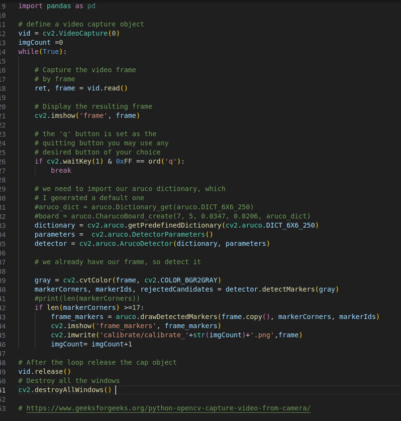
and paste the code below in it…
# import the opencv library import cv2 import numpy as np import cv2, PIL, os from cv2 import aruco from mpl_toolkits.mplot3d import Axes3D import matplotlib.pyplot as plt import matplotlib as mpl import pandas as pd # define a video capture object vid = cv2.VideoCapture(0) imgCount =0 while(True): # Capture the video frame # by frame ret, frame = vid.read() # Display the resulting frame cv2.imshow('frame', frame) # the 'q' button is set as the # quitting button you may use any # desired button of your choice if cv2.waitKey(1) & 0xFF == ord('q'): break # we need to import our aruco dictionary, which # I generated a default one #aruco_dict = aruco.Dictionary_get(aruco.DICT_6X6_250) #board = aruco.CharucoBoard_create(7, 5, 0.0347, 0.0206, aruco_dict) dictionary = cv2.aruco.getPredefinedDictionary(cv2.aruco.DICT_6X6_250) parameters = cv2.aruco.DetectorParameters() detector = cv2.aruco.ArucoDetector(dictionary, parameters) # we already have our frame, so detect it gray = cv2.cvtColor(frame, cv2.COLOR_BGR2GRAY) markerCorners, markerIds, rejectedCandidates = detector.detectMarkers(gray) if len(markerCorners) >=17: frame_markers = aruco.drawDetectedMarkers(frame.copy(), markerCorners, markerIds) cv2.imshow('frame_markers', frame_markers) cv2.imwrite('calibrate/calibrate_'+str(imgCount)+'.png',frame) imgCount= imgCount+1 # After the loop release the cap object vid.release() # Destroy all the windows cv2.destroyAllWindows()
|
(sorry about the indents I think the copy + paste didn't keep them... here is a picture to show what it supposed to look like)
Run the python file with:
python ./collectImages.py
When the images come up on the screen move around with the board, again making sure to keep the distance the same. Don’t sit in one place for too long because it is saving images as fast as it can. It won’t be able to read the board in a blurred image, so if you move it won’t see the markers until you stop for a moment. After a few seconds you should have a whole bunch of images in the calibrate folder. We’ll need this for the next step.
Calibrate Camera Using OpenCV
There is a example we can compile in the calib3d tutorial code. This one uses a “default.xml” file to specify the configuration rather than having a bunch of command line arguments, so to build it:
cd ~/opencv_build/opencv/samples/cpp/tutorial_code/calib3d/camera_calibration
g++ -ggdb camera_calibration.cpp -o camera_calibration `pkg-config --cflags --libs opencv`
This default.xml file contains the settings to use for the application. These settings specify the board size, board type (we can do more than charuco), what images it will use...etc.
You can copy the existing IN_VID5.xml file to default.xml as a base to modify.
cp in_VID5.xml default.xml
Now modify the default.xml with our settings…
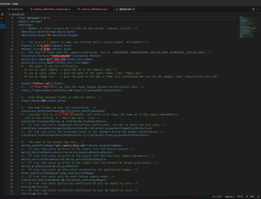
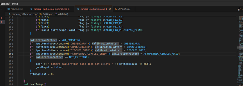
for the types of boards we can look at the example code we build and see what options there are.
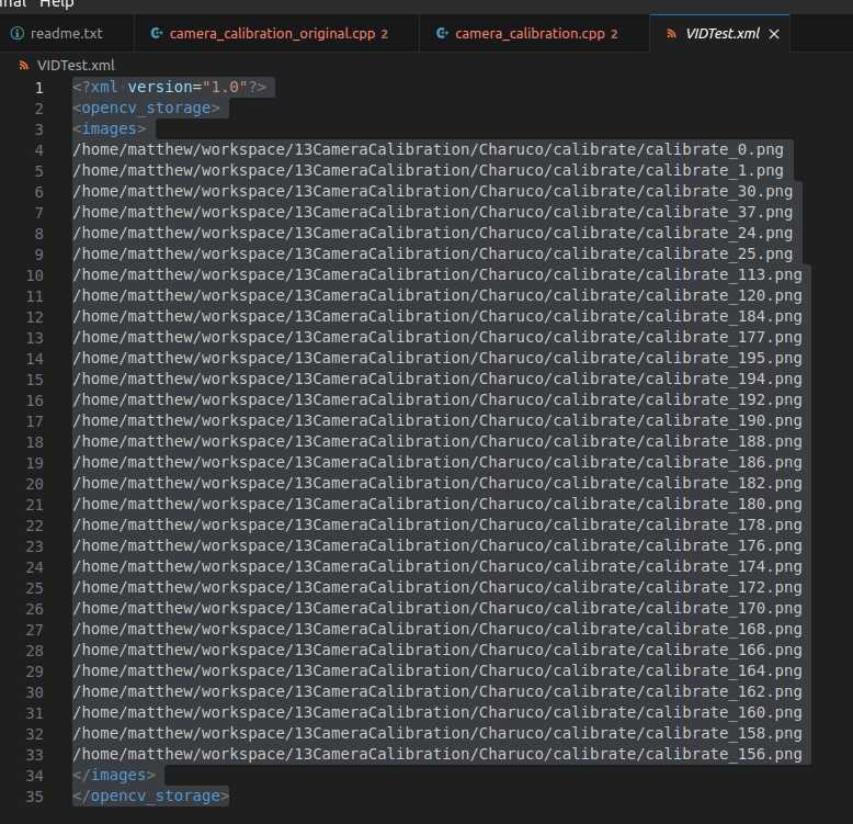
For the last file, which in my case I need because I am specifying where the images are located. I have to have at least the number of images I set in the default.xml to use for calibration. I told it I would use 25 images, so if I don’t have at least that the program will simply die without providing any information of why nor will it give us the camera matrix, so make sure there are enough images defined… You can also use a video stream to calibrate with, but I chose the image route since I already took them.
/home/matthew/workspace/13CameraCalibration/Charuco/calibrate/calibrate_0.png /home/matthew/workspace/13CameraCalibration/Charuco/calibrate/calibrate_1.png /home/matthew/workspace/13CameraCalibration/Charuco/calibrate/calibrate_30.png /home/matthew/workspace/13CameraCalibration/Charuco/calibrate/calibrate_37.png /home/matthew/workspace/13CameraCalibration/Charuco/calibrate/calibrate_24.png /home/matthew/workspace/13CameraCalibration/Charuco/calibrate/calibrate_25.png /home/matthew/workspace/13CameraCalibration/Charuco/calibrate/calibrate_113.png /home/matthew/workspace/13CameraCalibration/Charuco/calibrate/calibrate_120.png /home/matthew/workspace/13CameraCalibration/Charuco/calibrate/calibrate_184.png /home/matthew/workspace/13CameraCalibration/Charuco/calibrate/calibrate_177.png /home/matthew/workspace/13CameraCalibration/Charuco/calibrate/calibrate_195.png /home/matthew/workspace/13CameraCalibration/Charuco/calibrate/calibrate_194.png /home/matthew/workspace/13CameraCalibration/Charuco/calibrate/calibrate_192.png /home/matthew/workspace/13CameraCalibration/Charuco/calibrate/calibrate_190.png /home/matthew/workspace/13CameraCalibration/Charuco/calibrate/calibrate_188.png /home/matthew/workspace/13CameraCalibration/Charuco/calibrate/calibrate_186.png /home/matthew/workspace/13CameraCalibration/Charuco/calibrate/calibrate_182.png /home/matthew/workspace/13CameraCalibration/Charuco/calibrate/calibrate_180.png /home/matthew/workspace/13CameraCalibration/Charuco/calibrate/calibrate_178.png /home/matthew/workspace/13CameraCalibration/Charuco/calibrate/calibrate_176.png /home/matthew/workspace/13CameraCalibration/Charuco/calibrate/calibrate_174.png /home/matthew/workspace/13CameraCalibration/Charuco/calibrate/calibrate_172.png /home/matthew/workspace/13CameraCalibration/Charuco/calibrate/calibrate_170.png /home/matthew/workspace/13CameraCalibration/Charuco/calibrate/calibrate_168.png /home/matthew/workspace/13CameraCalibration/Charuco/calibrate/calibrate_166.png /home/matthew/workspace/13CameraCalibration/Charuco/calibrate/calibrate_164.png /home/matthew/workspace/13CameraCalibration/Charuco/calibrate/calibrate_162.png /home/matthew/workspace/13CameraCalibration/Charuco/calibrate/calibrate_160.png /home/matthew/workspace/13CameraCalibration/Charuco/calibrate/calibrate_158.png /home/matthew/workspace/13CameraCalibration/Charuco/calibrate/calibrate_156.png
|
Run the compiled app with:
./camera_calibration
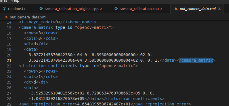
Now we have a file “out_camera_data.xml” and this file contains the matrices we need…

you can see the rows and columns are mentioned there in the xml. What must be kept in mind is you need to read this data from top down and left to right, so this 3x3 matrix is:
3.6272145870642380e+04 | 0 | 6.3950000000000000e+02 |
0 | 3.6272145870642380e+04 | 3.5950000000000000e+02 |
0 | 0 | 1 |
While it’s not important for our project here, but it’s helpful to know that the camera matrix contains the “focal lengths” and the “camera center” values. This is what the 4 fields specify. In other words we only need 4 values to create this matrix. Another way to look at this matrix looks like:
(fx, 0, offsetx,
0, fy, offsety,
0, 0, 1)
We will define it and the distortion coefficients in python like this:
cameraMatrix = np.array([[ 3.6272145870642380e+04, 0.0, 6.3950000000000000e+02 ],
[ 0., 3.6272145870642380e+04, 3.5950000000000000e+02],
[ 0., 0., 1.]])
distCoeffs = np.array([-3.9253296104015567e+02, 6.7280534769708663e+05, 0., 0., -1.0812339216870673e+09])
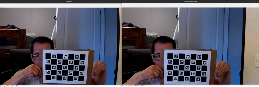
The python file to undistort an image is incredibly easy… all you have to do is use those matrices by applying them to an image with the undistort function.
img = cv2.undistort(frame.copy(), cameraMatrixInit,distCoeffsInit)
my file is “undistort.py”
import cv2import numpy as npimport cv2, PIL, osfrom mpl_toolkits.mplot3d import Axes3Dimport matplotlib.pyplot as pltimport matplotlib as mplimport pandas as pddatadir = "Charuco/calibrate/"images = np.array([datadir + f for f in os.listdir(datadir) if f.endswith(".png") ])order = np.argsort([int(p.split(".")[-2].split("_")[-1]) for p in images])images = images[order]allImages = []for im in images[150:155]:print("=> Processing image {0}".format(im))frame = cv2.imread(im)gray = cv2.cvtColor(frame, cv2.COLOR_BGR2GRAY)imsize = gray.shapecameraMatrixInit = np.array([[ 3.6272145870642380e+04, 0.0, 6.3950000000000000e+02 ],[ 0., 3.6272145870642380e+04, 3.5950000000000000e+02],[ 0., 0., 1.]])print("cameram matrix shape")print(cameraMatrixInit.shape)distCoeffsInit = np.array([-3.9253296104015567e+02, 6.7280534769708663e+05, 0., 0., -1.0812339216870673e+09])cv2.imshow('original', frame)img = cv2.undistort(frame.copy(), cameraMatrixInit,distCoeffsInit)cv2.imshow('undistoredFrame', img)# the 'q' button is set as the# quitting button you may use any# desired button of your choiceif cv2.waitKey(0) & 0xFF == ord('q'):# Destroy all the windowscv2.destroyAllWindows()quit()
you can see the rows and columns are mentioned there in the xml. What must be kept in mind is you need to read this data from top down and left to right, so this 3x3 matrix is:
3.6272145870642380e+04 | 0 | 6.3950000000000000e+02 |
0 | 3.6272145870642380e+04 | 3.5950000000000000e+02 |
0 | 0 | 1 |
While it’s not important for our project here, but it’s helpful to know that the camera matrix contains the “focal lengths” and the “camera center” values. This is what the 4 fields specify. In other words we only need 4 values to create this matrix. Another way to look at this matrix looks like:
(fx, 0, offsetx,
0, fy, offsety,
0, 0, 1)
We will define it and the distortion coefficients in python like this:
cameraMatrix = np.array([[ 3.6272145870642380e+04, 0.0, 6.3950000000000000e+02 ],
[ 0., 3.6272145870642380e+04, 3.5950000000000000e+02],
[ 0., 0., 1.]])
distCoeffs = np.array([-3.9253296104015567e+02, 6.7280534769708663e+05, 0., 0., -1.0812339216870673e+09])
The python file to undistort an image is incredibly easy… all you have to do is use those matrices by applying them to an image with the undistort function.
img = cv2.undistort(frame.copy(), cameraMatrixInit,distCoeffsInit)
my file is “undistort.py”
import cv2 import numpy as np import cv2, PIL, os from mpl_toolkits.mplot3d import Axes3D import matplotlib.pyplot as plt import matplotlib as mpl import pandas as pd
datadir = "Charuco/calibrate/" images = np.array([datadir + f for f in os.listdir(datadir) if f.endswith(".png") ]) order = np.argsort([int(p.split(".")[-2].split("_")[-1]) for p in images]) images = images[order]
allImages = [] for im in images[150:155]: print("=> Processing image {0}".format(im)) frame = cv2.imread(im) gray = cv2.cvtColor(frame, cv2.COLOR_BGR2GRAY) imsize = gray.shape
cameraMatrixInit = np.array([[ 3.6272145870642380e+04, 0.0, 6.3950000000000000e+02 ], [ 0., 3.6272145870642380e+04, 3.5950000000000000e+02], [ 0., 0., 1.]]) print("cameram matrix shape") print(cameraMatrixInit.shape) distCoeffsInit = np.array([-3.9253296104015567e+02, 6.7280534769708663e+05, 0., 0., -1.0812339216870673e+09])
cv2.imshow('original', frame)
img = cv2.undistort(frame.copy(), cameraMatrixInit,distCoeffsInit) cv2.imshow('undistoredFrame', img)
# the 'q' button is set as the # quitting button you may use any # desired button of your choice if cv2.waitKey(0) & 0xFF == ord('q'): # Destroy all the windows cv2.destroyAllWindows() quit()
|
To run the code we execute with:
python ./undistort.py
Sources:
https://docs.opencv.org/4.x/d7/d9f/tutorial_linux_install.html
https://neuraspike.com/blog/3-rookie-mistakes-people-make-installing-opencv-avoid-it/
https://www.skynats.com/blog/installing-opencv-on-ubuntu-20-04/
https://linuxhint.com/getting_started_opencv_ubuntu/
https://stackoverflow.com/questions/39379311/how-to-generate-a-charuco-board-calibration
looks like the API for the detection changed… it actually is a bit simpler.
in case use older patterns
https://github.com/opencv/opencv/issues/23873

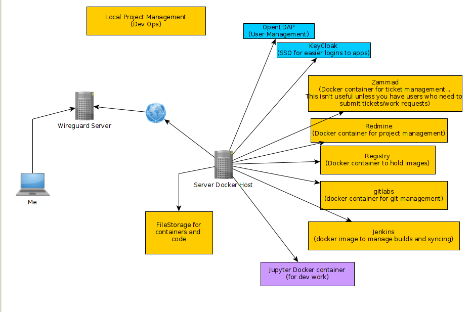
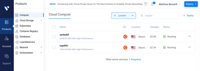
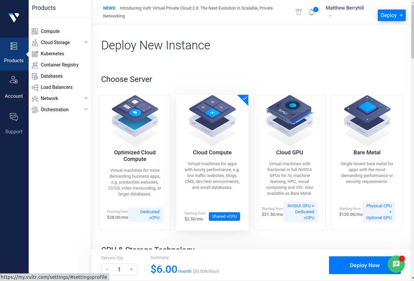
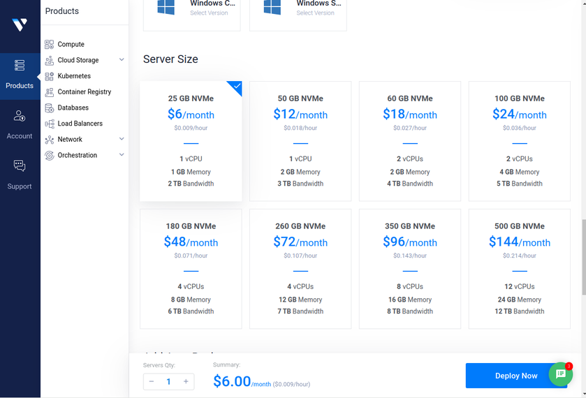
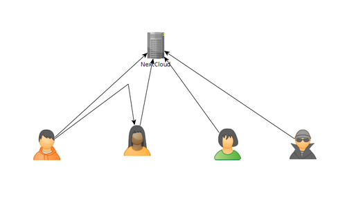
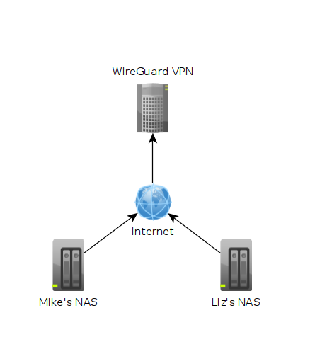 In the image above each machine is at a different location. One might be in Texas while another could be in Washington. The "Wireguard VPN" is the only one that we can directly talk to on the internet. In other words, it's the only one exposed publically. This machine is running on a cloud provider such as vultr.com or you can run it on amazon's cloud too. Vultr has machines with 1GB ram down to around $5, so I've been using them.
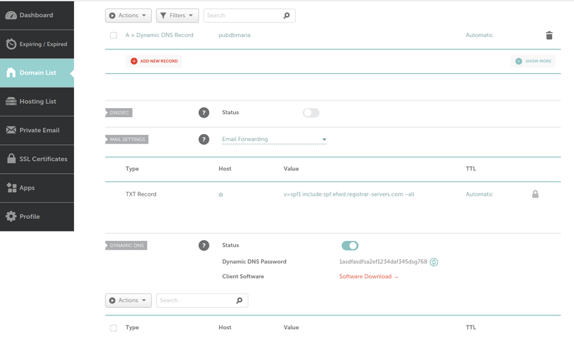
 What we can see in this image is that I own the xyz123.net on my account. That's the domain I own. I can add subdomains by clicking on "Manage" then click on "Advanced DNS". When the page loads click on "Add new Record" you want to make sure you pick "A+ Dunamic DNS Record" then for host you'd put the subdomain you want like "wireguard". When you try to access it, you would go to "wireguard.xyz123.net"... btw we aren't done on this page yet. We have to make sure we enable dynamic DNS clients...
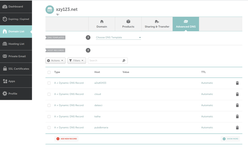
 As of today, there are some issues with this syncing. First one is that if a user A shared their files with another user B, that user B will immediately start downloading the files whether they want them or not. There is a feature you can enable to prevent automatically downloading if the filesize is too large. This helps mitigate issues but not completely. If someone really wanted to mess with others they could create shares up to that limit and simply spam the targeted user forcing them to download a ton of files just under that limit... I think the fix to this is to default to always asking the user if they want to accept a share and what to do with it, or even simply accept it but don't auto download.